CYPULL selection tool

Hydraulic Cylinder Configurator

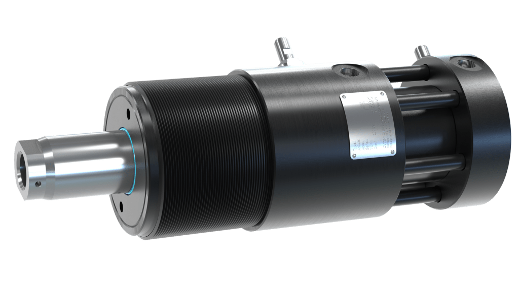
CYPULL a hydraulic locking core-pulling cylinders for mould design and construction. They combine high holding forces with a compact, extremely rigid structure, so the core reaches and keeps a defined end position even under high injection pressure.

CYTEC CYPULL – INJECTION LOCKING CYLINDERS

Cylinder Hydraulic
Round Cylinder
ZY3L
Block Cylinder
zubehoer1
Spare Parts
CYTEC Cylinder Configurator

CYTEC cylinder configurator

Switch between the CyPull core-pulling configurator and the full locking-cylinder series selector.

CYPULL locking core-pulling cylinders

Select a design and the technical requirements – or read how the cylinders work first.

What CYPULL cylinders do

CYPULL are hydraulic locking core-pulling cylinders for mould design and construction. They combine high holding forces with a compact, extremely rigid structure, so the core reaches and keeps a defined end position even under high injection pressure.

Because the locking is mechanical and self-inhibiting, the hydraulic pressure can be switched off once the cylinder is locked – for maximum process security and fast cycles.

Round vs. block design

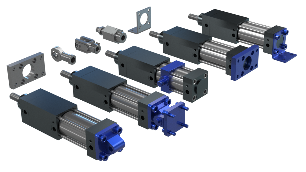
  • Round cylinder – nominal sizes 20–200 (piston Ø), rod Ø 14–140 mm. Optional round/square mounting flanges and lock nut.
  • Block cylinder – short-stroke, sizes 20–80, rod Ø 14–56 mm. Compact footprint for tight mould layouts.

Both share the same locking principle and reach holding forces from 32 up to 3.300 kN, depending on series and pressure.

Locking with preload (P)

The segments create an additional preload so the core reliably touches the mould surface. The cone-shaped contour lets the rod lock within a tolerance range up to 1 mm, compensating mould elasticities. The core does not recede during injection.

Locking without preload (L)

For a completely exposed core that does not touch. The piston rod is clamped with positive lock in the end position; pressure can be switched off once locked, for maximum operational safety.

How to size the cylinder

The holding force of the cylinder must exceed the process force. The process force follows from the injection pressure acting on the projected area:

F_process [kN] = p [bar] · A [mm²] · 10⁻⁴, with A = π/4 · (D² − d²) for a touching core.

Always keep a force reserve for safety – if the process force is close to the maximum holding force, choose the next larger series.

Sensors & monitoring

Inductive sensors detect the locking state and the end positions of the piston rod, contactless and wear-free. Available as:

  • PNP (up to 80 °C), PNP high-temperature (up to 120 °C) or NAMUR
  • Rod side (locked/extended) or piston side (retracted)
  • Straight or angled plug; retrofit for all standard series

Reading the order code

The configurator builds the full CYPULL order code automatically, for example CP-HR-P1E-063-036-0075-SLPS-SRPS-F-G. Each block has a meaning:

CP – core-pulling cylinder
H – hydraulic supply
R / B – round / block design
P / L – with / without preload
1E – locking principle / elastomer seal
063 – piston Ø [mm]
036 – rod Ø [mm]
0075 – stroke length [mm]
SL.. / SR.. – sensors (rod / piston side)
F G N KO KS – accessories

Matching cylinders

Pre-selection only. Final cylinder sizing, holding force, sensors, mounting components and control variants must be confirmed by CYTEC before ordering. Dimensioning condition: holding force of the cylinder must exceed the process force (Fprocess = p · A).

CYTEC cylinder selector

Choose a locking cylinder series, pick the piston size, then build the order code.

Two locking principles

Positive-locking cylinders (CyLock HA/HB, CyPull, CyLock PV, CyLock PT) lock in the end position with utmost holding force. The holding force is independent of the fluid pressure – pressure can be switched off once locked. Spiral-spring operated mechanism, two pressure ports.

Friction-holding stop cylinders (CyStop KP) stop in every possible position. Stop force equals stroke force, with a safety stop on pressure drop. Disc-spring operated, three pressure ports, pneumatic only.

The five series

  • CyLock HA/HB – hydraulic, holding 20–880 kN, piston Ø 25–125.
  • CyPull – hydraulic core-pulling cylinder for injection moulding, up to 3.300 kN.
  • CyLock PV – pneumatic, cylindrical locking, play locking, 13–314 kN.
  • CyLock PT – pneumatic, conic locking (HS-type), no locking play, 31–140 kN.
  • CyStop KP – pneumatic friction stop, 0,7–60 kN, free positioning.

Locking end position

Most series are available in three locking types:

  • 01 rod side (standard) – locks with extended piston rod
  • 02 piston side (option) – locks with retracted rod
  • 03 rod / piston side (option) – locks in both end positions

Sensors & sizing

Inductive sensors detect the locking state and end positions, contactless and wear-free (cable or plug, PNP or NAMUR, Reed switch for stroke detection). Reed switch adds 10 mm cylinder length.

Sizing condition: the holding force of the cylinder must exceed the process force. Keep a force reserve and confirm final sizing with CYTEC.

Reading the order code

Each series builds its own code. Example HA/HB: HA-080-01-0150-SR-F. Each block has a meaning:

HA/HB – series
080 – piston Ø [mm]
01/02/03 – locking end position
0150 – stroke [mm]
SR / SN – sensor (PNP / NAMUR)
RD – Reed switch (+10 mm)

Matching cylinder series

Pre-selection only. Final cylinder sizing, holding force, locking end position, sensors, mounting components and control variants must be confirmed by CYTEC before ordering. Dimensioning condition: holding force of the cylinder must exceed the process force.

CYLOCK / CYSTOP/